ã€China Deep Hole Rig Trading Network】 1. Improper selection of the oil number of the long-auger hydraulic oil may cause the hydraulic system to generate heat. The selected hydraulic oil will work normally when the oil temperature is low, but after the system is working for a period of time, the oil temperature will rise and the viscosity of the hydraulic oil will decrease. As a result, the internal leakage of the system has increased, and along with the increase of the leakage, the oil temperature has increased and the vicious circle of oil temperature has formed. The solution is: According to the system load and normal operating temperature requirements, select the appropriate viscosity of hydraulic oil. 2. Unreasonable design of the fuel tank reduces the cooling effect of the hydraulic system. The main function of the heating oil tank is to store hydraulic oil, but it also has the functions of heat dissipation, sedimentation, and moisture separation. Fuel tank design is irrational, mainly in two aspects: First, the fuel tank volume design is too small, because the long spiral drill rig is completed after the concrete pump is a mobile hydraulic equipment, fuel tank volume is generally about double the hydraulic pump flow, therefore, The fuel tank heat dissipation area and oil storage capacity are small. Second, some fuel tanks are unreasonably designed in structure. The suction nozzles and the return nozzles are close to each other, and there are no partitions in the middle, thereby shortening the cooling cycle of oil in the tank. And the path of precipitated impurities, even causing most of the oil return directly into the suction pipe, so that the cooling effect of the tank decreases, the oil temperature rises. The solution is: increase the volume of the fuel tank appropriately so that the volume of the fuel tank is (1125-115)Q, and try to increase the distance between the suction nozzle and the return nozzle. Separate the partition between the suction and return pipes to ensure The fuel tank should have cooling power. 3. The cooling flow is small, the cooler installation position is unreasonable, and the cooling capacity of the system is reduced. After the long spiral drilling rig is completed, the cooling method of the concrete pump is air-cooled and water-cooled. Users can choose according to the actual situation, but generally adopt the wind. More cold. After some long spiral drilling rigs are piled, the concrete pump is installed on the oil return road of the mixing system due to the pressure requirement of the cooler. Only the oil of the stirring system is cooled. Because the agitation system has a small flow, the whole The cooling effect of the system is poor, causing the system to heat up. The solution: First, an independent cooling circuit can be used to improve the cooling effect. The second is to set the cooler on the total oil return of the system to increase the cooling flow and improve the cooling effect. However, two problems should be noticed at this time. The first problem is the speed of the cooling fan, and the speed of the cooling fan should not be too low. Otherwise, the cooling effect will be reduced. A motor-driven fan may be used, or a low-pressure drive motor may be installed on the total return road to match the speed of the motor with the heat dissipation flow, and also to solve the influence of the main circuit pressure shock on the pressure bearing capacity of the cooler; The second problem is that if a motor-driven fan is used, the pressure shock of the main system will affect the pressure bearing capacity of the cooler. At this time, a low-pressure overflow protection valve or one-way valve pair cooling can be installed on the return oil line together with the cooler. The highest pressure protection of the device. 4. The improper selection of hydraulic components causes the system heating. The concrete pump hydraulic system is generally a high-pressure and large-flow system after the pile is completed. If the hydraulic components in the system are mainly selected by the reversing valve, overflow valve and sequence valve Unreasonable, can not meet the large flow requirements, so that in use, so that the valve port flow velocity is too high, resulting in greater pressure loss and increase the oil temperature, therefore, the hydraulic system design in the hydraulic component selection design It is necessary to select the components according to the maximum working pressure, the maximum flow rate, and the required pressure and flow adjustment range of the hydraulic components, so as to minimize the pressure loss at the valve ports, thereby reducing the unreasonable selection of hydraulic components. The system is hot. 5. The design and installation of pipelines are unreasonable, resulting in large pressure loss, so that pressure can be converted into thermal energy. In the design of hydraulic systems, the design and installation of pipelines can not be ignored. The pipeline diameter of each pipeline should be strictly according to its working pressure and flow rate. The design is carried out to avoid that the pipe diameter is too small and the flow rate is too high. The pressure loss along the way is too large, causing heat. At the same time, attention should also be paid to the installation of pipelines, which should not only achieve a neat appearance, but also avoid pipe agglomeration and sharp turn of pipelines, affect the natural heat dissipation of pipelines or cause excessive pressure loss caused by partial heating. The heating problem of the concrete pump hydraulic system in the process of the long auger drilling machine has become one of the problems that can not be ignored. Due to the heating of the hydraulic system, many failures of the concrete pump after the completion of the long auger drilling machine will occur. For the concrete pump manufacturer after the completion of the long spiral drilling rig of Henan Sanli Machinery, the company should try to start from the design and reduce the heat of the hydraulic system to the lowest value. This will not only improve the user's long-auger drilling rig after the completion of the concrete pump. Rate and prolong its service life, but also can save energy and reduce maintenance costs; for the concrete pump users after the completion of the long auger drilling machine, should strive to start with the use of maintenance, in strict accordance with the requirements of the manufacturer, the correct use, commissioning, inspection, maintenance of long Auger concrete pump after the completion of the pile to reduce the failure rate and reduce system heating caused by improper use. In short, after taking certain measures for the different causes of heat generation, the heat of the hydraulic system can be controlled or reduced, and the operating rate of the concrete pump and the prolonged service life of the long spiral drilling rig can be improved. For more information, please pay attention to the China Deep Hole Rig Trading Network ()
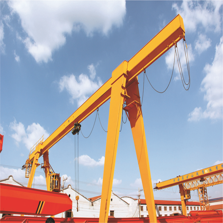
MH Type Electric Hoist Girder Gantry Crane is used together with CD MD Model electric hoist. It can be matched with various electric wire rope hoist and chain hoist, to meet the different requirements of customers to improve the working efficiency. It adopts the optimized design of main beam to keep the strong stability and stable braking and precise location when crane in the low dead weight. It is the best solution of light load and short span.
This product is a regular crane widely used at open ground and warehouses to load, unload or grab materials. It has two controlling methods: ground control and cabin room control.
We can provide you all kinds of MH type Electric Hoist Gantry Crane, truss gantry crane, other accessories are also available such: Crane Remote Control, Insulated conductor Rail and Hoist Hook , and also the Grab Bucket , with us you can enjoy the one stop service.
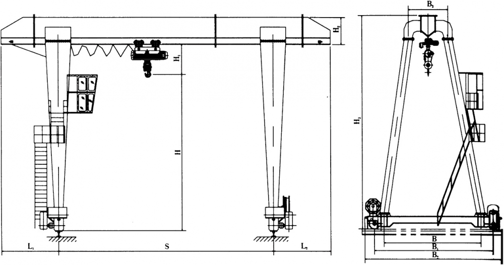
Sketch
Parameter
Lifting Capacity
T
3
5
10
16
20
Operation method
Pendent line with push button/ cabin
speed
Lifting
m/min
8, 8/0.8
8, 8/0.8
7, 7/0.7
3.5
3.5
Cross travelling
20
20
20
20
20
Long travelling
ground
20
20
20
20
20
cabin
30, 40
30, 40
30, 40
30, 40
30, 40
Motor
Lifting travelling
Type/kw
ZD41-4/4.5
ZD141-4/7.5
ZDS10.8/4.5
ZD151-4/13
ZDS11.5/4.5
ZD151-4/13
ZD152-4/18
Cross travelling
ZDY12-4/0.4
ZDY121-4/0.8
ZDY21-4/0.8×2
ZDY21-4/0.8×2
YZD-4/0.8×4
Long travelling
ground
ZDY21-4/0.8×2
YZR132M1-6/2.2×2
YZR160M1-6/6.3×2
YZR160M1-6/6.3×2
YZR160M1-6/
6.3×2
ZDY21-4/1.5×2
YZR132M2-6/3.7×2
YZR160M2-6/8.5×2
YZR160M2-6/
8.5×2
cabin
ZDR22-4/1.5×2
YZR132M2-6/3.7×2
YZR160M1-6/6.3×2
YZR160M2-6/8.5×2
YZR160M2-6/
8.5×2
ZDR24-4/2.2×2
YZR160M1-6/5.5×2
YZR160L2-6/11×2
YZR160L2-6
/11×2
Electric hoist
Type
CD1/MD1
CD1/MD1
CD1/MD1
CD1
CD1
Lifting height
m
6,9
Working duty
A5
Power supply
380V 50HZ 3phase AC
Span
m
12,16,20,24,30
Detailed image
Single Girder Gantry Crane Single Girder Gantry Crane,Single Girder Goliath Crane,Single Beam Gantry Crane,Electric Hoist Gantry Crane Jiangxi Mide Industrial Co., Ltd. , https://www.midecrane.com


