Liquid Capsule Filling Sealing Machine Wenzhou Grand Machinery Technology Co., Ltd. , https://www.dagemachinery.com
Figure 1 shows the electrical IV characteristic of a typical diode. Although a complete test procedure can include hundreds of points, exploration of a limited sample is generally sufficient to provide merit. Many HB LED tests require a known current source to drive the device and measure its voltage accordingly, or vice versa. Simultaneously having a synchronizable signal source and measurement function can speed up system setup and increase throughput. Testing can be done at the die level (wafer and package) or module/subassembly level. At the module/subassembly level, HBLEDs can be connected in series and/or in parallel; thus, higher currents are generally required, sometimes up to 50 A or more, depending on the application. Some die-level tests use currents in the range of 5 to 10A, depending on the size of the die. 
1. Forward Voltage Testing To understand how new building block materials, such as graphene, carbon nanotubes, silicon nanowires, or quantum dots, play their role in future electronic devices, it must be used Measurements of resistance, resistivity, mobility, and conductivity are measured on a range. This often requires measurement of extremely low currents and voltages. For engineers who are trying to develop and commercialize these next-generation materials, the ability to make accurate, repeatable measurements at the nanoscale is extremely important.
2. Leakage current test When a reverse voltage below the breakdown voltage is applied, the measurement of the leakage current (IL) across the HBLED generally uses a moderate voltage value. In production testing, it is common practice to ensure that the leakage current does not exceed a certain threshold.
3, improve the throughput of HBLED production test In the past, all aspects of production testing of HBLED are controlled by a single PC. In other words, in each element of the test program, the signal source and measuring device must be configured for each test, and after executing the expected actions, the secretary is returned to the PC. The control PC proceeds according to the pass/fail criteria. Evaluate and decide which category the DUT should fall into. The process of sending instructions and results back to the PC by the PC will take a lot of time.
The latest generation of smart devices, including Keithley's latest high-power 2651A System Source/Meter (SourceMeter), can significantly increase test throughput by minimizing traffic for communications. The main body of the test program is embedded in a Test Processor (TSP) in the instrument, which is a test program engine for controlling the test procedure, with built-in pass/fail control of standards, calculations, and digital I/O. A TSP can store user-defined test programs in memory and execute the program according to the user's needs, thereby reducing the setup and configuration time of each step in the test program. 
4, single device LED test system 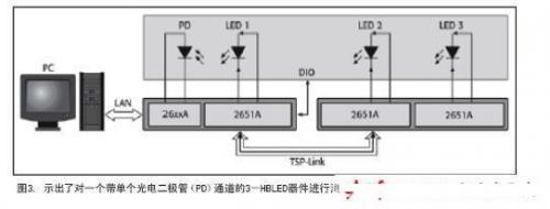
The component controller transports a single HBLED (or group of HBLEDs) to a test fixture that shields ambient light and has a photodetector (PD) for light measurement. Two SMUs are required: SMU #1 provides the test signal to the HBLED and measures its electrical response; SMU #2 detects the photodetector during the optical measurement process.
The test program can be programmed to start on a digital signal line from the component controller as a "test start" (SOT) control. When the instrument detects this signal, the test program starts. Once the execution is completed, a digital signal line from the component manipulator is issued with a "test completed" flag. In addition, the instrument's built-in intelligence can perform all pass/fail manipulations and send digital instructions to the component manipulator through the instrument's digital I/O ports to allow HBLEDs to classify HBLEDs based on pass/fail criteria. It is then possible to program two actions simultaneously: the data is sent to the PC for statistical processing, while a new DUT is transported to the test fixture.
5, optical test Optical measurement also need to use the forward current bias, because the current is closely related to the amount of light emitted by the HBLED. A photodiode or integrating sphere can be used to capture the emitted photons so that the optical power can be measured. The light emission can be converted into a current and measured with a current meter or a single channel of a signal source-measurement unit.
6. Reverse breakdown voltage test Reverse bias current applied to HBLED can achieve reverse breakdown voltage (VR) test. The test current should be set so that the measured voltage no longer rises significantly with a slight increase in current. At higher voltages, the reverse voltage change caused by a large increase in reverse bias current is not significant. The test method for VR is to output a low reverse bias current for a specific period of time and then measure the voltage drop across the HBLED. The result is generally tens of volts.
High brightness light emitting diodes (HBLEDs) combine high output, high efficiency, and long life. Manufacturers are developing devices that can achieve higher luminous flux, longer life, more color, and higher luminance per unit of power. To ensure its performance and reliability, accurate, cost-effective testing must be performed at each stage of production.
Figure 1 Typical HBLED DCI-V curves and test points (not drawn to scale)